
Note, normally, the voltage is 12V, only certain the chip needs higher voltage, then it sets up to voltage above 12V. when press this switch, the voltage cycles among 12V, 15V, 21V, 25V, and the voltage can be read from LED. VPP Setting Switch: to configure 27series chip programming voltage. Special Chip Switch: to configure the 2732, 2716, 2816, I28F001, AT29C256 special chips, when press this switch, the internal circuits automatically switch between those chips, the status is directly indicated by the LED. There is a Safety Jumper located on the top of the board. In the above picture shows three black color buttons. They are: Reset Swithc, VPP Setting Switch and Special Chip Switch.

On the middle top of the board, three push button switches. Please note only one chip programming is allowed at the same time, otherwise the error will occur when programming or chip may be damaged. They are DIP32, PLCC32, FWH/LPC, 25CXX, 24CXX, 93CXX, PIC16F84 and etc. The blue portion is the socket of the target chips. If the connection and power supply is normal, then appears: "Hardware present"
#WILLEM PROGRAMMER WINDOWS 7 SOFTWARE#
Software Operation The software interface:Īfter start the program, click test hardware under Help menu, if the power supply or connection is wrong, appears the prompt, please check if the programmer connects well with
#WILLEM PROGRAMMER WINDOWS 7 PC#
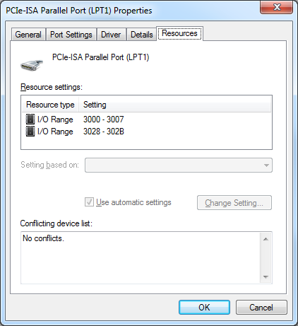
Note: the LPT port of PC needs setting to ECP or ECP+EPP during BIOS setup.ģ. Then, the two programmer normal indicators light up, then the programmer power supply is normal, the hardware connection is ok. Turn off PC power supply Connect one end of the cable to PC printer port Connect the other end to 25 Pins port of the programmer Connect A-A type (Male-Male) USB cable to the programmer and PC. The hardware is fully compatible with original Willem EPROM Programmer (PCB3B) and Windows software. Added PLCC32, FWH/LPC and P28F002BC adapters on board. The USB cable is A-A type Male-to-Male connector. Added a USB port to make use of USB power. And Reset key provides a quicker way to reset VPP and Special Chip configuration to normal state. Safety Jumper will disable all VPP and Special Chip changing to avoid misconfiguring accidentally. Added a Safety Jumper and a Reset key to gave more protection when programming. There are 7 LEDs to indicate the chip type been selected currently.(Normal, 2732, 2716, i28F, AT29, W27C) 4. The special chip selection key provides a simple way to select a chip type by pressing the Special Chip key. There are 4 LEDs to indicate the VPP currently been selected. For this Enhanced Willem EPROM Programmer, VPP can be configured by just press the VPP setting key. So that to protect this programmer not be damaged by mis-configured VPP jumper. Added isolation circuit (between VPP and pin). What's new about this Enhanced Willem EPROM Programmer from PCB3B?ġ. 18 Willem Programmer Supported Device List. Enhanced Willem EPROM Programmer – ManualĬontent What's new about this Enhanced Willem EPROM Programmer from PCB3B?.


 0 kommentar(er)
